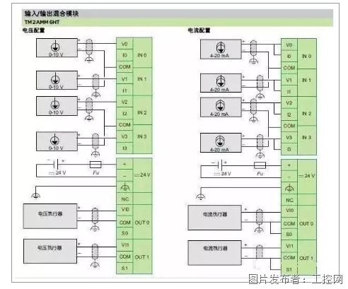
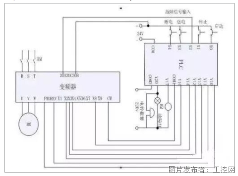
During the debugging process of PLC projects, any strange problems can be encountered, and signal interference is one of them. It is difficult to find the cause of the problem. Today we will share two cases, an example of frequency converter interference with PLC analog signals, and a solution to overcome such interference using signal isolation modules.
Example 1
Phenomenon explanation
The AO point in Siemens PLC sends a 4-20mA current control signal, which is output to the Siemens frequency converter, but cannot control the startup of the frequency converter.
Fault finding
1. Suspected analog output board issue, measure the 4-20mA output signal with a multimeter, and the signal is normal!
2. I began to suspect that there was a problem with the control signal input of the frequency converter. I replaced it with a frequency converter of the same model, but the problem still persists.
3. We used a handheld signal transmitter as a 4-20mA output signal source, outputting a standard current signal to the frequency converter. As a result, the frequency converter started, and we ruled out faults with the analog output board and frequency converter.
4. It can be inferred that the interference signal from the frequency converter is transmitted to the analog channel.
5. To verify, a signal isolation module TA3012 was installed in the 4-20mA output channel of the PLC analog signal. Input terminals 5 and 6 of TA3012 were connected to the analog output module, output terminals 1 and 2 were connected to the frequency converter, and terminals 3 and 4 were connected to an external 24VDC power supply. The frequency converter started normally.
6. Based on this, it can be concluded that the root cause of the problem lies in the interference of the frequency converter with the analog channel.
matters needing attention
In an automatic control system where PLC and frequency converter are used simultaneously, the following precautions should be emphasized:
1. The PLC power supply and power system power supply (frequency converter power supply) should be configured separately, and the PLC power supply should choose an isolation transformer.
2. The power line should be separated from the signal line as much as possible, and the signal line should be shielded.
3. Both analog signal input and analog signal output use signal isolation modules for analog channels.
4. Design software filtering in PLC programs.
5. Separate the design of signal ground and power ground.
Example 2
Recently, I saw an analysis and solution to the problem of analog interference, and in our practical application, we will encounter many similar problems. Let’s share with everyone: “There are 10 250KW motors in the workshop, loaded with high-pressure pumps. The frequency converter is connected to the PLC through DP using Schneider ATV71, and the PLC uses Siemens 300. The pressure transmitter is Siemens, and the analog signal from the transmitter to the PLC is 4-20mA, with a shielded wire input in the middle.”.
After debugging, everything runs normally for a week. After the manufacturer left, pump number 8 suddenly appeared when starting up, with a set pressure of 40 kilograms and an actual value of 70 kilograms. Set the actual pressure of 80 kilograms to 110 kilograms. At first, I suspected a sensor malfunction and replaced it with another pump. Everything was normal. Afterwards, the frequency converter was fully turned on, and similar problems occurred with pumps 3, 4, 5, 6, 7, 9, and 10. It is speculated that the pressure sensor is affected by frequency converter interference. The manufacturer suggests adding metal tube shielding. However, considering the difficulty of on-site construction (the control room is more than 30 meters away from the motor and all cables are laid in underground cable trenches).
And I believe that the harmonic interference of the frequency converter should be caused by fluctuations in pressure values, and it is rare to see interference causing a linear increase. At first, I suspected that there was a problem with the manufacturer’s program because the pressure value displayed on the display screen was always 40 kilograms, but the frequency converter was outputting 70 kilograms. The manufacturer disagrees with this viewpoint, stating that they absolutely use Siemens standard PID blocks.
I can’t figure it out after much contemplation. Accidentally discovered that the negative and shielding layers of the manufacturer’s sensor were simultaneously connected to the M of the PLC analog input terminal. Remove the shielding wire and connect it to the ground fault of the device to eliminate it. Speculation: A 2-wire sensor with a PLC providing 24V voltage on the positive pole and a 4-20mA current output on the negative pole. After the shielding wire is connected to the negative electrode, the induced electromotive force on the shielding wire generates a current that enters the PLC input terminal together, resulting in a superimposed current and a linear increase in pressure value.
After only 2 days of operation, the same situation occurred again, and even more serious was that one of the pressure sensors was removed and there was still 40 kilograms of pressure. After final inspection, it was found that the negative electrode of the PLC input side was stripped and elongated, causing a short circuit between them and causing signals from other channels to string out. I just remembered that when I first started debugging, the manufacturer asked me if the equipment floor and cabinet floor were not on the same floor. After grounding the shielding wire of the pressure sensor, the interference is particularly severe. None of them can be displayed. I didn’t think much and casually said, single ended grounding. Afterwards, they agreed. Now, thinking about it, it should be that the current output side of each sensor was connected together through shielded wires, causing a short circuit, and then the ground wire on the sensor side was removed. Due to the shielding wires not being connected together, the signal is normal.


